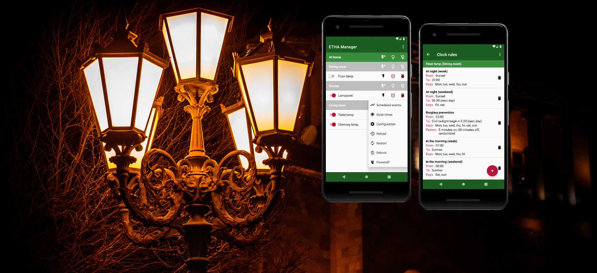

Here’s where we assemble, test and build the finalized version of the hardware components of the ETHA Light Switch.
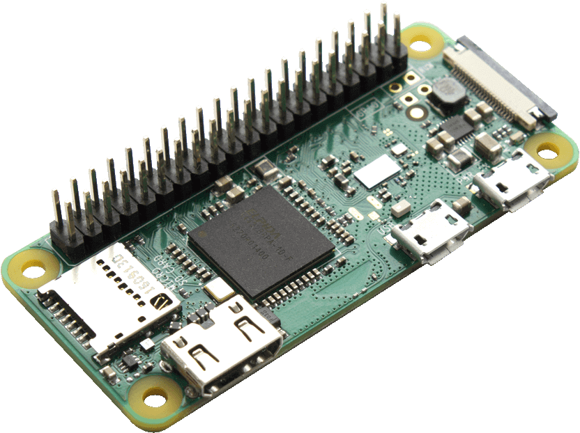
First we need a Raspberry Pi Zero W. Make sure you buy the W version, otherwise you’ll end up not having a WiFi connection. I bought the version with pre-soldered header. The advantage of that is that you don’t have to solder anything on the Raspberry Pi Zero W itself.
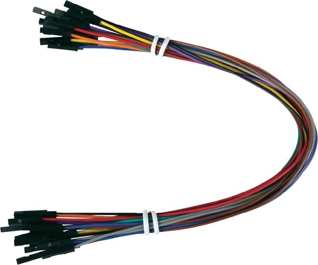
You can then buy some jumper cables in various lengths. You can cut off one end, or cut the cable in half, to make a connection between the Raspberry Pi Zero W and a soldered endpoint. Some types of jumper cable come with additional pins to configure a male or a female connection.
To test the hardware a breadboard comes in handy. Together with the jumper cables it becomes easy to make connections with various components and test them.

Specific hardware
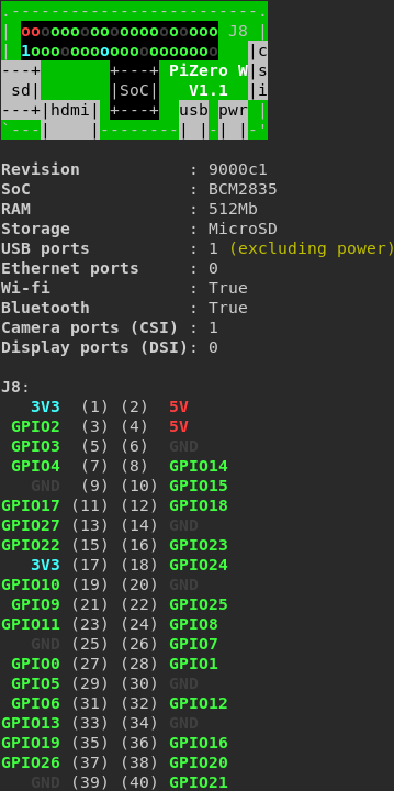
Before listing all the specific hardware needed for the ETHA Light Switch, let me show you the circuit diagram.
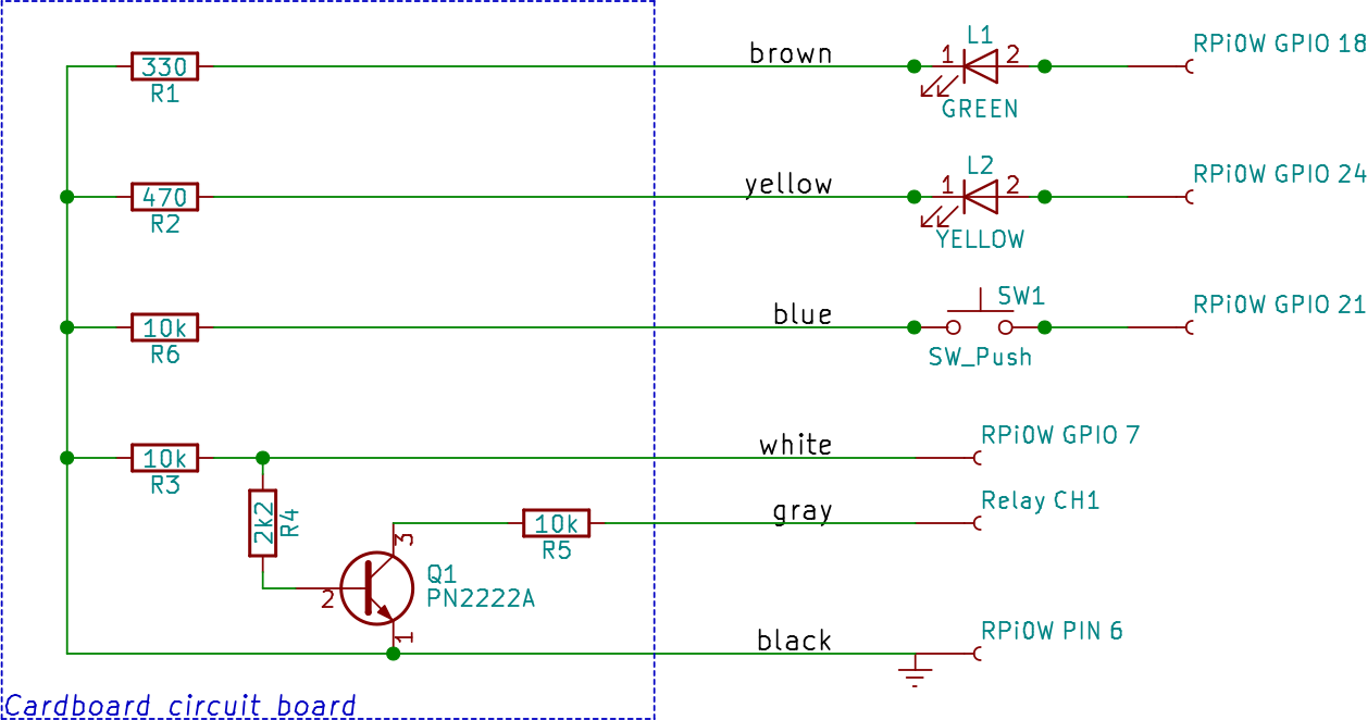
All the components are explained below. The GPIO connections to the Raspberry Pi Zero W are just my choice. You can choose others. Beware: the numbers are the BCM numbers, not the board numbers (except for ground, pin 6). If you install the package python3-gpiozero (apt-get install python3-gpiozero) you can use the pinout command to show all the correct numbers. The numbers in brackets are the pin numbers of the header; all other numbers are GPIO (BCM) numbers.
R1 and R2
These are resistors to protect the LEDs from too much current and burning. The recommended value is 330 Ω, but I noticed that my yellow LED was burning much brighter than my green LED, so I used 470 Ω for R2. You can also try higher values.
R6
A resistor of 10 kΩ. The GPIO port connected to SW1 just needs to go to a low state, not burn the Raspberry Pi Zero W.
R3, R4, R5 and Q1
This is the most complicated circuit. This circuit switches the relay from the GPIO port of the Raspberry Pi Zero W.
Why is it so complicated? Well, the relay I used switches on when its channel goes to the low state. I wanted to reverse that because when the Raspberry Pi Zero W is powered on, the GPIO ports are low. But then the relay and the connected lamp switch on immediately. So with this circuit consisting of three resistors (R3 and R5 are 10 kΩ, R4 is 2.2 kΩ) and one transistor (Q1 is a PN2222A, a general purpose NPN transistor) I made sure that the relay switches on when, and only when, the GPIO port goes high.
It’s actually quite simple: the GPIO’s high state opens the transistor and pulls the relay channel to low.
L1 and L2
The LEDs I used are standard 5 mm LEDs. Of course you can pick any color you want, as long as you know which has what function.
SW1
Any off/(on) switch will do. It is an off/(on) switch, which means a switch that short-circuits the two connections when it is pushed, and immediatly breaks the circuit when it is released. The on position is never “held”. This is important because the software is depending on this type of switch. Maybe a future release will support other types of switches. (Come to think of it: in some situations it may be useful to support, for instance, a normal wall (off/on) switch.)
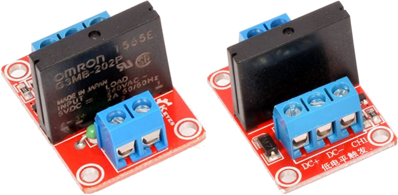
Relay
I used a relay board with a 2 A solid-state relay. You can also use an electromagnetic relay board which is capable of switching larger currents, if you don’t mind the clicking noise. For the purpose of switching lamps 2 A is more than enough. At a mains voltage of 230 V (Europe) you can switch 460 VA according to the formula S(VA) = V(V) × I(A). So as long as you’re not switching electric kettles or vacuum cleaners, you’re good to go.
Testing
So now it’s time to put it all together in a testing environment. For the time being we’re not building the final form, because this way it’s a lot easier to correct mistakes. So here’s the complete ETHA Light Switch in a test setup.
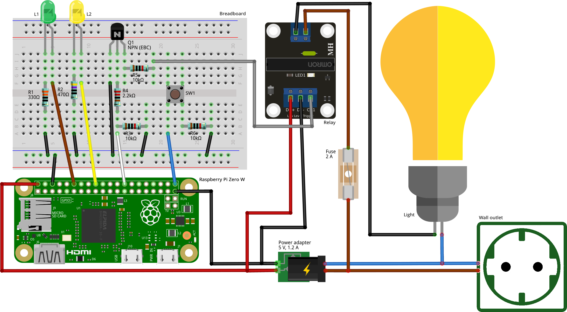
Some remarks about the ETHA Light Switch testing diagram:
- The cable colors and (GPIO) pin numbers correspond with the circuit diagram above.
- The 5 V power supply is connected directly to the Raspberry Pi Zero W pins. This can do no harm, as the Raspberry Pi Zero W (in contrast to other Raspberry Pi models) doesn’t have a protective circuitry to shield from overcharging.
- The switch I used here (SW1) is a breadboard switch, not the one used in the final version.
- Mind the polarity of the LEDs and the transistor! The order of the transistor pins in the testing diagram is (from left to right): emitter, base and collector (EBC).
- I connected the power input for the relay (pins DC+ and DC-) directly to the power supply, not via the Raspberry Pi Zero W. The other pin is the channel (switch) pin (CH1).
- I added a fuse of 2 A to protect the relay. If you accidentally connect a vacuum cleaner to the ETHA Light Switch, the fuse will be blown and not the relay and the rest of the circuitry (hopefully).
Well that’s about it. Now it’s is testing time. If you’ve not done it already, you can install and prepare the operating system on the sd-card (Preparing the Raspberry Pi Zero W), install and configure the ETHA Light Switch Python program (Installing ETHA Light Switch on the Raspberry Pi Zero W and Configuring ETHA Light Switch). It is also a good idea to read all about MQTT (MQTT in ETHA Light Switch).
The definitive version
Once testing goes well, let’s now build a final version. Depending on your situation you have multiple choices of how to implement ETHA Light Switch. You can build it, for instance, in a meter cupboard (fusebox) or, if there’s enough room, even inside a wall outlet. If not, there are thousands of different enclosures on the market. Only your fantasy is the limit.
For my first ETHA Light Switch project I chose a connector housing.
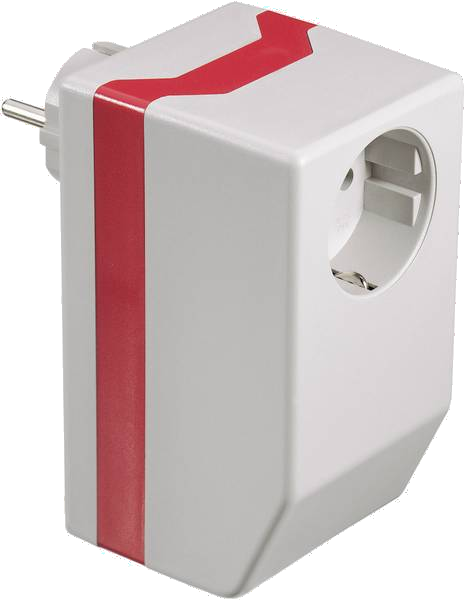
This particular model is made by Strapubox. I had to buy the red ring, which enlarges the housing, separately, but I didn’t need it after all. There was (just) enough room in it to house all the parts:
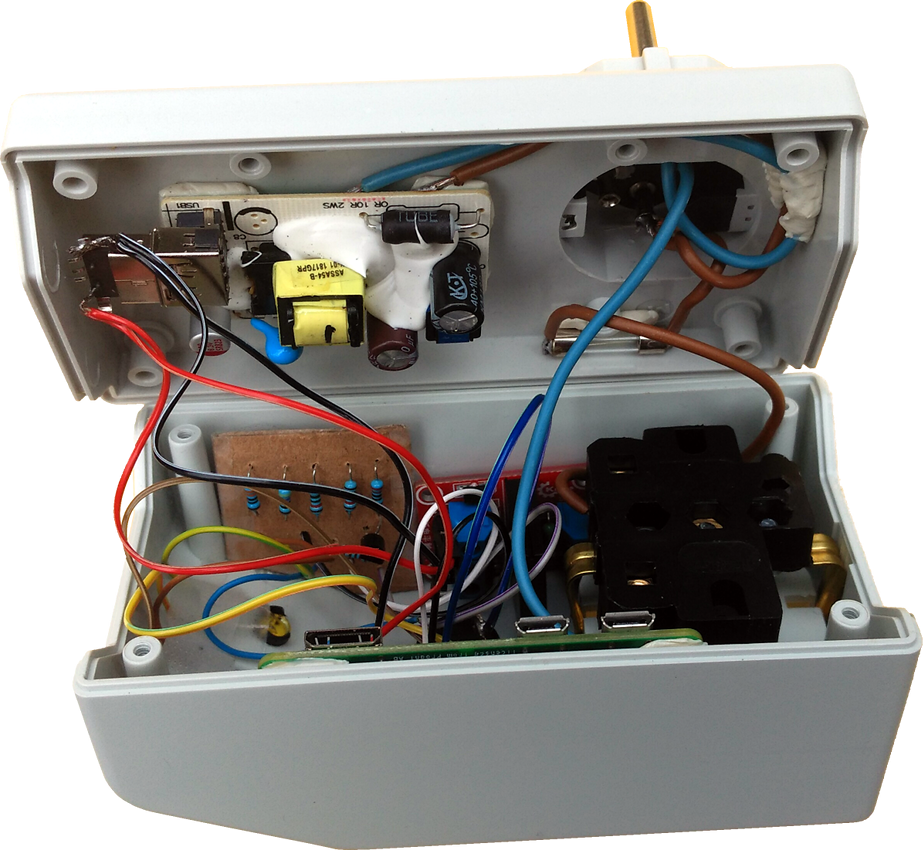
So how do we get all the components in a more or less orderly fashion into the housing? The first problem I encountered was that although there are screw holes at the inside of the housing, none of the components are fitting them. So in the end I used something called adhesive putty to stick the components to the side of the housing. That works really well!
Now we can begin to fit all the components into the housing.
Housing connectors
When we open the Strapubox we can see the mains power connectors (the two big black blobs on the image above). One is input and the other (the largest blob) is the output to the lamp. To the input connector we need to solder two power cables to each of the pins (I used a standard electrical wire). One pair goes to the 5 V adapter, and the other pair to the output connector (one of the wires via the relay board and the fuse).
In some countries (for instance the UK) you have to mind the polarity of the power connectors (line and neutral). In other countries this is not a problem, since power plugs fit both ways.
Power adapter
Power adapters are not hard to come by. This is a 5 V adapter capable of delivering a minimum of 1.2 A at the ouput (this is recommended for the Raspberry Pi Zero W). We all have them lying scattered around our houses. I used a version with a USB output connector. The problem is that these adapters have a housing of their own. So we have to demolish that housing first. It cost me half an hour, a hacksaw, a screwdriver and two minor injuries to my hand to accomplish that! I then soldered one pair of power wires to the input side of the adapter. I also soldered two pairs of jumper cables to the 5V output of the adapter (one pair leading to the Raspberry Pi Zero W and the other to the relay board). Here I used a type-A USB connector.
LEDs and switch
We have to drill some holes in the connector for the two LEDs and the switch. For the LEDs I used a small LED fitting. So I had to drill two 6 mm (5 mm plus the size needed for the fitting) holes for the LEDs and one 16 mm hole for the switch. I used a standard wood drill for the small holes and a spade bit for the larger hole. Keep in mind that you drill your holes while one side of the housing rests on a big piece of wood for solidity and preventing the housing from damage outside the hole.
Cardboard circuit board
I fixed the components on the breadboard shown above in the ETHA Light Switch testing diagram (except for the LEDs and the switch) on a tiny peace of cardboard, cut out to fit the assigned space. See also the circuit diagram of ETHA Light Switch where these components are marked on the cardboard circuit board. You can stick the resistors through the cardboard and solder them together with the needed jumper cables on the back. After that fix the soldering on the back of the cardboard with some kind of tape to prevent shortcircuiting.
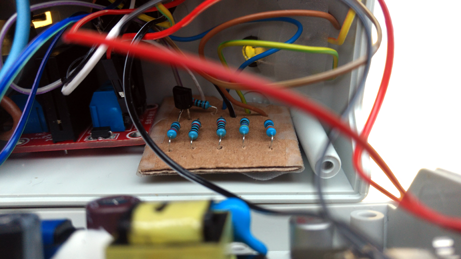
Another way of doing this is to use a universal printed circuit board, but that probably takes up more space.